While both linear and rotary servo motors use high-performance custom servo motor cables to transmit energy and provide close feedback signals, the basic nature of their movements places different demands on cable design, routing, and durability. By understanding the differences between linear and rotary servo motors, OEM engineers can avoid common specification errors that cause early wear, signal noise, or costly downtime in motion control systems.
This guide presents a comparison of the two applications from a cable point-of-view, highlighting the mechanical stresses, routing considerations, EMC factors and best practice for specifications that a typical machine builder will face in the real world.
Linear vs Rotary Servo Motors – Why Cable Requirements Change
Unlike mechanical servos that convert motion to other forms, such as ballscrews or belts, linear servo motors generate force straight along a track. The torque produced by rotary servos is usually transfered to linear motion via mechanical components. Although both cables are powered and both are feedback cables, they are quite different in terms of physical layout, travel distance, and dynamic stress.
Such differences directly affect cable flex life, tolerance to cable torsion, cable shielding and connector strategies, particularly for high duty cycle automation equipment.
Common Servo Cable Roles in Both Motor Types
Power and Feedback Functions Are Similar
In either system, servo cables usually contain several pairs of conductors for low-voltage feedback signals, such as those from an encoder or resolver, as well as power conductors that supply the motor. Understanding servo power, feedback, encoder, and brake cable types helps engineers define the correct electrical architecture for precise position, speed, and torque control.
Both Can Be Static or Dynamic
Either static or dynamic motion can occur in the cables for either type of motor. The selection always takes into account the duty cycle, bend radius and environmental exposure of the motor, not just the motor classification.
The differences in physical layout and routing.The differences in physical layout and routing.
Physical Layout and Routing Differences
Rotary Motors: Compact, Localized Cable Routing
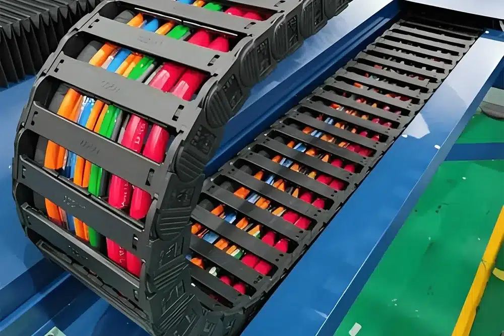
In most cases, rotary servo motors are installed on brackets with cables exiting from one connector. Routing commonly includes short bends close to the motor and limited travel in axis-following cable carriers. Follow best practices for installing cables in drag chains when arranging these routes with other services and providing strain relief.
Linear Motors: Long Tracks and Distributed Cable Paths
Linear servo motors have a moving primary (forcer) that travels along a fixed magnetic track. Cables must cover long, straight runs and often operate close to strong magnetic fields. To choose drag chain cables for CNC linear axes, evaluate continuous support throughout the stroke to minimize sagging and excessive vibration exposure.
Mechanical Stress Differences on Servo Cables
Rotary Axes – Bend and Torsion Around a Compact Motor
This is because repeated bending is typically included in Rotary applications in the carrier whilst there is also some degree of localized torsion near the motor connector as the axis rotates or articulates. Twisting resistance: cables are designed to resist twisting without causing damage to shields or conductors.
Linear Axes – Long-Stroke Flexing and Vibration
Linear direct-drive systems provide high acceleration and long travels. Cables experience millions of bending cycles over long strokes, in addition to steady vibrations and possible exposure to strong magnets in iron core cable designs.
Selecting Flex-Rated Cables According to Motion Profile
Match cable construction to the dominant motion: use continuous-flex designs for long-stroke linear axes and torsion-resistant designs where rotary motion concentrates stress. See specifying servo cables for static, flexing, and torsional applications for a practical specification framework. Travel length, speed, and acceleration are more important selection factors than motor type alone.
Feedback and EMC Considerations in Linear vs Rotary Systems
Feedback Cables in Linear Motor Systems
Long-stroke linear axes require high-resolution feedback over greater distances. Custom cables for high-precision servo and motion control systems help preserve signal integrity in the presence of magnetic fields and mechanical noise. Good shielding and suitable separation from power lines remain essential.
Feedback Cables in Rotary Servo Motors
Rotary encoders are frequently installed in a small motor casing, which increases the distance between the motor and the encoders (feedback runs). Although protection against EMI is still significant, most routing distances are more comfortable to deal with.
EMC Shielding and Routing Differences
Both applications require shielded servo cables to reduce electromagnetic interference. Linear installations may require additional consideration around magnetic tracks, while rotary installations require compact separation between carriers and cabinet entry points. Apply shielding strategies and grounding best practices for servo motor cables in either case to help maintain system performance.
Connector and Interface Differences
Rotary Servo Motor Connectors
Standardized round or rectangular connectors are provided on the motor housing for power, brake, and feedback. Engineers should verify servo motor OEM pinouts and connectors while allowing for local flex and torsion where cable assemblies connect to these interfaces.
Linear Motor Cable Interfaces
Connectors can be connected to the moving forcer, junction boxes or distributed points on the track. Flexible saddles or intermediate support frequently are used in design for reliable long travel performance, with shield continuity.
Specification Differences OEM Engineers Should Capture
Use this servo cable selection checklist for new machine designs to document the following application inputs before finalizing a cable design.
Motion and Routing Inputs
- The type of motor (linear or rotary)
- The length of travel, speed and acceleration
- Cable carrier, free hanging
- A bending radius and torsion exposure are required.A bend radius and torsion exposure is required.
- The vibrations and shocks are being measured.
Electrical and Feedback Needs
- The voltage and current required for the power source.Power supply requirements or supply voltage and current.
- The feedback protocol comprises the encoder, resolver and digital components.
- Protection level and EMC environment cover protection from the elements and EMC environment.
- The maximum length of cable for signals.
Environment and Protection
- Contact with coolants, oils, chips or chemicals.
- The ambient temperature and humidity range from
- Requires special jackets (PUR, TPE, etc.)
Practical Summary for OEM Cable Strategy
Use cable assemblies designed specifically for rotary servo motor axes with mechanical conversion, compact routing, localized bend/torsion, and standard connectors. Where sustained rotational stress is present, consider custom torsion cable solutions designed for the required twisting duty. For direct-drive linear servo motors, select cables with long-stroke flex performance, strong EMC shielding, and mechanical support along the track.
If possible, use multi-purpose cable families that are suitable for both applications and make certain that there are clear differences in the specific cables used to ensure maintenance teams can operate without confusion. The right specification upfront, using real motion profiles, lowers life cycle costs and machine reliability.
Whether you use a servo motor cable in a rotary or linear application for robotics, CNC, or industrial automation, Hulk Electric can provide a custom servo cable solution matched to these requirements. Submit your axis parameters, and our engineers can help you choose or tailor the best solution for long-term performance.