

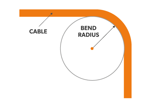
There’s one simple, yet often forgotten step that can cause a lot of cable failures in industrial automation, robotics and high-cycle motion applications: bending it too tightly or flexing it over its rated minimum bend radius or flex life over repeated motion. Minimum bend radius refers to the smallest bend that the cable can make without causing any damage to the conductor or insulation, and flex life is the number of bending cycles that the cable can withstand before it fails. By knowing and respecting these two parameters, unexpected downtime is avoided, signal errors are avoided, and costly replacement of drag chains, robotic arms and servo systems can be avoided.
After 20 years of manufacturing high flexible cables, servo cables, robot torsion cables, and industrial Ethernet solutions, we have seen how the correct bend radius selection directly lengthens the cable life and the reliability of the system at Hulk Electric. This guide presents the concepts, how they interact, and their application to your designs.
What Is Minimum Bend Radius?
Minimum bend radius is the smallest radius that the cable can be bent without any mechanical or electrical damage. Its value is usually specified in multiples of the outer diameter (OD) of the cable, e.g., 5× OD, 7.5× OD or 10× OD. The measurement is taken inwards to the bend curve.
This specification provides protection against excessive strain on the internal conductors, insulation and shielding during installation and operation. Going over the limit, even once, can cause the damage to start, which can get worse over time.
Basic Definition and How It’s Expressed
The minimum bend radius can be calculated from the simple formula:
The Minimum Bend Radius is Cable OD × Multiplier (as listed by the manufacturer, static or dynamic).
For instance, in motion applications, a 10 mm outside diameter (OD) cable with a 10x dynamic bend radius should have a minimum of 100 mm inside radius. For dynamic (moving) applications, always refer to the datasheet to ensure that the radius is sufficiently large; static (fixed) applications require smaller radii.
Typical Rules of Thumb by Cable Type
There are different types of cables with varying capacities:
- Typical power or control cable for fixed installation: typically 6–8× OD.
- Cables: Mostly 7.5–12× OD or greater, depending on the construction; highflex and continuous-motion cables (drag chain, servo, robot): common sizes 7.5–12× OD or more, depending on construction
- Specialized torsion or ultra-flex cables for robotics — can be used on tighter radius curves, but still needs to be checked.
Hulk’s high-flexible cables and robot cables are designed for dynamic use, providing optimised stranding and jacketing for cable performance within rated limits.
What Is Flex Life and How Is It Measured?
The flexibility life is the number of bending cycles a cable will endure under specified conditions before failure (splitting of conductor or cracking of the insulation). These ratings such as “5 million cycles” or “20 million cycles” are based on standard laboratory tests for comparison and give a guideline on how long the product is expected to last.
Flex Life as Number of Cycles to Failure
Flex life is a measure of durability in a continuous-motion environment in real applications. A cable tested for 10 million cycles could have long service life in a drag chain when it is used for several shifts a day, as long as bend radius, rate, travel distance and temperature are within the limits.
Test Setups and Key Parameters
The flex life is determined by manufacturers by means of double-loop drag chain simulators, pulley bend rigs or combined torsion setups that mimic actual flex action. These are: bend radius, cycle speed, acceleration, travel length, temperature and mechanical load. Any variations in these have a significant impact on results and is important to indicate conditions in datasheets.
How Bend Radius and Flex Life Interact
The biggest enemies of cable longevity are tighter bends and more counts. The two parameters are directly related: operating at a closer minimum bend radius will cause faster fatigue rates and reduce flex life.
Why Tighter Bends Increase Internal Stress
When a cable is bent, tension is applied to the outside and compression to the inside of the cable. The more differential strain that is applied to conductors, insulation, and shields, the smaller the radius. This results in work-hardening of the copper strands, formation of micro-cracks in the jackets and deformation of the shields over repeated cycles, which is undetectable until failure occurs.
Trade-Off Between Radius and Lifetime
The flex life is significantly increased with a larger bend radius. The cable life in cycles can be 10-20 million times longer at the minimum dynamic radius at 1.5-2 times the minimum dynamic radius. In practice consider the minimum bend radius as a minimum. For high cycle applications, add margin, for more service life and less maintenance.
Real-World Effects of Ignoring Minimum Bend Radius
Failure to follow bend radius recommendations can result in needless production downtime and cost.
Mechanical Damage: Kinks, Jacket Cracks and Conductor Breaks
Typical symptoms are kinking at sharp corners, flattening of cables, cracking of the outer jacket and ultimately open circuits due to broken conductors. These problems tend to manifest themselves close to clamps, entry glands or the most constricted area within a cable carrier.
Electrical and EMC Issues from Deformed Geometry
Over bending can cause internal conductor(s) to move, which changes the conductor position and can affect shielding, thereby changing the impedance and increasing EMI. This can lead to noisy encoder signals, fieldbus or Ethernet communication errors or unexpected drive faults, despite the fact that the cable looks fine from the outside.
Applying Minimum Bend Radius in Design and Installation
Cables undergo their service life as per their rated performance with appropriate routing and installation.
Calculating and Checking Bend Radius in Layouts
Always determine the necessary size of the radius by the manufacturer’s multiplier and check each bend in the system, such as pulleys, guides, glands and cable carriers. For dynamic applications provide additional clearance for movement, vibration and potential misalignment over time.
Design Practices for High-Cycle Motion (Drag Chains and Robots)
Use cable carriers whose radius is equal to or greater than the cable that has the largest radius in the bundle. Do not use connectors near sharp corners or tight loops. Employ correct strain reliefs for flexing in only the required areas. If you need more information on the correct drag chain configuration, or on how to install cables on a robot, check our resources on Industrial Flexible Cables and Servo Motor Cables.
Selecting Cables with the Right Bend Radius and Flex-Life Ratings
The first step in picking the right cable is to read the datasheet and communicate with the supplier.
Reading Datasheets: Bend Radius, Flex-Life and Test Notes
Check for static bend radius and dynamic bend radius values, and flex-life values and their test conditions. Hulk is a reputable brand that offers clear information for fixed, occasional flex and continuous motion conditions.
Questions to Ask Cable Suppliers
- What is the minimum bend radius for this cable when it is dynamic?
- What data is available regarding flex-life?
- Do you have a separate rating for linear drag chain and torsional movement?
- What is the safety margin required for my cycle, speed and environment?
Providing the complete motion profile allows the supplier to suggest the best construction.
Practical Design Checklist for Bend Radius and Flex Life
Before Finalizing Cable Routing
- Practical Design Checklist for Bend Radius and Flex Life
- Before Finalizing Cable Routing
- Confirm cable OD and manufacturer’s minimum bend radius.
- Check all bends, pulleys and carrier radii against or exceed dynamic requirements.
- For high cycle or high speed applications, add margin.
Before Approving Cable Specifications
- Make sure no unintentional twisting/torsion is added.
- Prior to the approval of cable specifications
- Plan for flex usage based on anticipated cycles of use.
- Align the cable with the type of application (standard flex, continuous-flex or torsion-rated).
- Verify jacket and insulation materials are appropriate for use in operating conditions.
- Check the test data to make sure that it meets your bend radius and lifetime requirements.



